Home › Forums › Design and Building › 2 Stroke Amplifier Design and Building › 2 Stroke kit build.
- This topic has 14 replies, 4 voices, and was last updated October 3, 2014 at 7:02 pm by
 Robin.
-
AuthorPosts
-
May 30, 2014 at 10:36 pm #5154
Spooks
ParticipantChassis
1. Output jacks for speakers. Am I fitting these into the two rear center holes that they seem to fit into nicely? Or are these holes for the rubber grommets? If the latter, am I drilling holes for the output speakers jacks, if so where?
2. On the outside front of chassis. Number 1 hole I think is for the input jack and number 2 hole is for the smaller switch.
3. Output Transformer. I assume I am fitting this to outside rear of chassis. Are ther supposed to be holes or am I drilling them myself?Ta for any help.
June 3, 2014 at 1:14 am #6004Andy
KeymasterThere are 2 ways to do the output jacks for the speakers. The book calls for two speaker jacks, and the kit provides parts for this. In this scenario, you will need to drill a new hole for the second jack, right near the first one. The existing hole is the one between the 9-pin tube cutout and the 8 pin tube socket cutout. You will also need to drill a hole for the impedance switch, typically to the far side between the 9-pin preamp tube cutout and the outer wall of the chassis.
That said, I only use one output jack, even for the two speakers. I wire the speakers in parallel if I use 2 speakers like the book calls for. It it the exact same as wiring the jacks in parallel (as the book states) and running speaker wire to each speaker individually.
For question 2, it doesn’t really matter, whatever makes sense for you. I do it just as you described.
Three, this goes on the largest flat surface. I usually use one of the predrilled holes and then drill another with the PT at an angle.
June 6, 2014 at 4:49 am #6005 RobinParticipant
Regarding the output transformer; it’s important to keep it toward the “power supply” end of the chassis, away from the input jack and to position it so the coil winding are perpendicular to the power transformer as much as possible. There are many explanations about transformer placement on the web, following the recommendations, you will minimize the potential for the transformer placement creating or contributing too hum and noise. It is possible to “tune” transformer placement for the lowest noise by moving the transformer around (slightly) on the finished chassis.
June 9, 2014 at 12:02 am #6006ParticipantSorry for the late reply. I have spent a week in Texas having fun, never took a laptop. Now back at the ranch. Those photos are brill, worth more than a hundred words. .
June 10, 2014 at 9:08 pm #6007ParticipantMoving along with the soldering, ta for the advice. I plan to build the amp cabinet from plywood until I find a donor cab or build a better one. I have looked on the net but not found any dimensions. Looking at a photo on a website, I think the speaker baffle board is 20″ x 20″ x 1/2″ . The casing looks 3/4″ x 9″ wide and length to fit outside dimension on baffle board. This is the site I found the photos on.
http://twostrokeamplifierbuild.blogspot.com/June 12, 2014 at 2:54 am #6008RobinParticipantYou could refer to the “Maggie” cabinet dimensions on the WeberSVT site, it’s a Two Stroke clone. Or use the info in DH’s book. I’ve found that the Two Strokes sound great in a open back, pine cabinet.
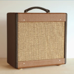
If you want to buy a finished cab, I have a brand new, pro built cabinet similar to the red one I use for my user logo here on the TAN site for sale. It’s solid pine with a baltic birch baffle (cut for 1-12, but a 8/10 combo speaker layout will fit) with a D2H custom cover. It’s brand new, never had a speaker or chassis installed in it. It’s two-tone brown and white (vintage looking). Send me a private message if you’re interested.
June 16, 2014 at 10:31 pm #6009ParticipantDid I reply to this? I apologise if I forgot.
September 24, 2014 at 1:01 am #6016ParticipantThe amp is altogether. All that is left is the cable from the output jack to the speakers.
1. As I only have one output jack, does this mean I can only use one speaker at a time?
2. With one wire soldered to the bullet TIP
( going into the OUTPUT jack ) and the other on the ring connection. Does it matter which speaker terminal the TIP connection wire is fitted to?Ta for all the help.
September 24, 2014 at 3:08 am #6017KeymasterNope, you can still use both speakers.
The TIP connection on the PLUG goes to POSITIVE on the speaker. Then the SLEEVE goes to the the negative on the speaker. Then you can wire from the POSITIVE on one speaker to the POSITIVE on the other speaker, and then the NEGATIVE of one to the NEGATIVE of the other.
This is a parallel wiring scheme and will cut your overall impedance in half. So if you have 2 8Ω speakers, they would present to the amp as a 4Ω load.
Personally, I like the single jack option better. But after using a Two Stroke for a long time, I don’t disconnect one or the other speaker. Its pretty fab with both.
a.
September 24, 2014 at 5:17 am #6018ParticipantWired up the speakers and switched on the amp. The two big valves light up, the small one glows also. No sound, not even a buzz. I guess I will be looking in the garage for the multimeter tomorrow.
September 25, 2014 at 8:02 pm #6019RobinParticipantDouble check the wiring from the input jack to V1, only the insulated wire should be connected, the shielding goes to ground on one end only. Refer to the updated schematic on the wiki pages or any tweed era fender schematic.
September 25, 2014 at 9:03 pm #6020ParticipantAs far as I can tell ( without disconnecting the cable ) the fat wire is connected to the input without the shield. It is now under the shrink wrap, a stray shield wire maybe touching the input connection? I did cut it back as per instructions. The other end of shield is soldered to earth. The middle cable is on number two (2) of V1.
I have noticed that one of the green wires from the PT to pilot light, it may have been touching both connections? Also the same green wire going to the middle valve ( V2), there is a right/wrong way to connect them to poles 2 and 7..September 26, 2014 at 9:55 am #6021RobinParticipantThe 6.3v twisted pair heater circuit sounds likes you have it wired correctly if the tube filiments are heating up. There may be an issue with noise (hum) but you can address that when the amp is working.
The layout illustration in the book and on the revised layout is confusing about the wiring for the input jack. See the schematic in the wiki section for a clearer view of how the input jack is wired. You can confirm it’s wired correctly with a multimeter or by simply pluging a guitar cord into the input jack (do not connect the other end of the cord to anything), there should be a 60hz hum when you touch the cord. If you try this test and the amp remains silent, chances are that the tip of input jack is wired to ground. To be clear, the center wire from the shielded cable should go from the tip lug of the input jack to pin 2 of V1 (the 12ax7 tube). You may have the 68k resistor in between the input jack and pin 2 (but if you leave it out, nothing bad will happen). Remember that the input jack is a “shorting jack” and intended to keep the amp silent when nothing is plugged in, the tip lug should test to ground when nothing is plugged in, but test open (not grounded) when a cord is plugged in.
October 2, 2014 at 12:53 am #6022Lee
ParticipantRobin, do you still have the cabinet for sale? Please advise…
October 3, 2014 at 7:02 pm #6023RobinParticipantYes, the cabinet is still available
-
AuthorPosts
- You must be logged in to reply to this topic.