Home › Forums › Design and Building › 2 Stroke Amplifier Design and Building › Building a 2 Stroke head
- This topic has 21 replies, 4 voices, and was last updated July 6, 2012 at 12:54 pm by
 Robin.
-
AuthorPosts
-
November 27, 2011 at 8:24 am #5200
 RobinParticipant
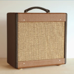
[attachment=22]2strokehead.1.jpg[/attachment]
I’ve just started a new 2 Stroke head. So far, I made the pine shell and purchased a Hammond 13.5″ x 2″ x 5″ aluminum chassis. This build will include a selectable rectifier (tube and solid state). My past amp builds have used eyelet or turret component boards, so this time I going to try a true “point to point” build using terminal strips and no component board. I hope to document the process as I go along and post it here. This is my third 2 Stroke amp.This scratch building process requires a bit of planning and foresight and does not guarantee a successful outcome, so if you are watching this unfold and have not built an amp before, I would recommend that you consider the T.A.N. kit as a first amp project as it allows you to focus on the actual assembly process and not have spend the time to spec all the components and layout the chassis. The TAN kit follows Dave Hunter’s design from The Guitar Amp Handbook (the updated, single tube version).
Next up: deciding on the transformer, tube socket and terminal strip placements and cutting the holes.
More detailed photos of the completed 2Stroke head are here:
https://www.tubeampnetwork.com/tan-community/74-robin/photos/album?albumid=23December 7, 2011 at 8:53 am #5505RobinParticipant[attachment=24]Chassisb.jpg[/attachment]
[attachment=25]Chassisd.jpg[/attachment]
The transformer & IEC socket holes were cut with a Unibit step drill bit to make the corners and a Dremel tool to cut between the corner holes, the tube socket holes and the rest were all cut with a Unibit. The terminal strips are laid out so the preamp section faces between the input jack and pots and V1, the filter caps face the power and rectifier tubes. Pardon the grey plastic covering on the exterior of the chassis, that will go away as I get a little farther along. Next up: mating the chassis with the cabinet and acquiring the last few components for this build.December 9, 2011 at 8:03 am #5506Andy
KeymasterLooking nice so far!
Did you draw up the plans for what will go where? And what is your plan for grounding?
December 9, 2011 at 9:12 am #5507RobinParticipantThe trick was getting the tubes and transformers on one side of a chassis that is approximately the same size as the TAN Two Stoke chassis. I’m using a Fender Deluxe PT which is a little bigger than the originally spec-ed Weber PT. The components were arranged in the chassis for best fit. I’m trying to keep the wiring lengths to a minimum. The preamp circuit will all ground with the pots and input jack. The filter caps will ground with the power section grounds to (I think) a grounding lug under one of the PT bolts. Although, there are so many ground terminals available on the terminal strips, I may end up using one of those. My other 2Strokes are hum-free, that’s what I’m aiming for.
December 12, 2011 at 10:09 am #5508RobinParticipant[attachment=27]ChassisG.jpg[/attachment]
[attachment=26]ChassisE.jpg[/attachment]
Chassis complete with sockets, switches, and jacks. Next up: Transformers and filament circuit wiring.December 20, 2011 at 2:41 am #5522RobinParticipant[attachment=29]Transformers1.jpg[/attachment]
[attachment=30]Heater1.jpg[/attachment]
[attachment=28]centertap1.jpg[/attachment]
The transformers are in, the power transformer wiring is complete.
Because the PT did not include a center tap for the 6.3v taps, an artificial center tap is added as a ground reference for the heater (filament) circuit and provide hum cancelling. Note the 100 ohm resistors connected between each side of the 6.3v circuit and ground. These 100 ohm resistors were selected from several resistors as a matched pair (99.6 ohms in this case) so that each side of the circuit will balance with the other. It is also possible to substitute a trim pot (220 ohm) between the two 6.3v leads to perfectly balance each side for maximum hum-cancelling.The fuse and pilot light wiring is messy at this point, these components will have to be removed from the chassis when the front and back panels are attached and the wiring willing be reinstalled more neatly at that time. The panels are in the works.
Note the tightly twisted pair of wires of the heater circuit, this too provides hum cancelling for the circuit.
Next up: Wiring the sockets and pots, and adding components.
January 2, 2012 at 9:52 am #5560RobinParticipantMost of the components have been installed. Adding the diodes and wiring the switch for the solid state side of the rectifier circuit is all that is left to do. The terminal strip layout seems to have worked out well, the leads have mostly been kept short, the grounds for the preamp section and power sections of the layout have been kept separate from each other.
At initial power-up, a Variac will be used slowly bring up the voltages and gently form the capacitors. A current limiter will be used to protect the components in case a mistake was made in wiring up the circuit.
Next up: finishing the SS rectifier circuit, powering up the amp and working on completing the cabinet. The front and back control panels are still to come.
I see that this topic has been viewed often, please feel free to comment or ask questions.
January 5, 2012 at 9:51 am #5561RobinParticipant[attachment=42]ChassisAA.jpg[/attachment]
The chassis is complete, the solid state rectifier circuit is installed on the unused lugs of the rectifier tube socket. The amp has been been brought up to full voltage and works great. Next up: finishing the cabinet and completing the front and back panels.January 7, 2012 at 7:07 am #5566ChasO
ParticipantRobin,
Looks very nice and clean inside. Now we all want to hear it
 . How is it heat wise as well? I noticed that my combo 2 stroke gets very warm. The Chassis is not quite too hot to touch but it gets hot (looked inside and everything seems fine). Seems like that would be an issue with an amp head where there is more metal to be touched and a more enclosed space. Do you need a fan or anything like that? Just curious.January 7, 2012 at 8:39 am #5567RobinParticipant
I’ll see about some sound samples. This one sounds at least as good as the others, maybe a little tighter bottom with the bigger transformer and SS rectifier.
Amps in class A tend to run warmer than other amps, the first Vox AC-30s use to burst into flames. I have several single-ended, class A amps and they all run hot. I am building the head cabinet with ports in the front for “flow-thru” ventilation (similar to a Two Rock cabinet). I don’t expect to need a fan. I run my other Two Strokes wide open all the time and although they get hot, I’ve not had a problem, it’s not much power.
I have yet to post any info on the new 30 watt amp I recently built similar to the original AC-30 (no top boost) or a Dr Z Stang-ray, (4-EL-84s) but I added Vox style vents to the combo cabinet after seeing how warm the chassis gets. With the vents added, it runs at a reasonable temp., even after being on for several hours.
May 18, 2012 at 10:10 am #5612RobinParticipantThe finished 2Stroke based head. Note that the selectable rectifier switch has been relocated to the back panel and the front panel now includes a standby (mute) switch. Finished photos of the back panel and interior to follow
[attachment=43]RC8front.jpg[/attachment]May 19, 2012 at 3:35 am #5614KeymasterLooks fab. Where did you have the faceplate done?
May 19, 2012 at 5:47 am #5616RobinParticipantJeanne at BNP lasers, we tried doing them here but they weren’t looking too good, so I figured I’d get some made by an established amp panel engraver and see what happens. Jeanne was very helpful in getting my CorelDraw files in order too. I purchased CorelDraw just for this project. I’ve learned a lot from this process and see ways to improve the design that will make the next ones look even better.
These look first class.May 19, 2012 at 5:51 am #5617KeymasterYeah they look really nice. Love that brushed and lasered look.
I have used Etched Media for screening. We did a flat plate that was powder coated and they screened directly. They did great work too. Check them out for the future. Great folks.
May 30, 2012 at 8:31 am #5623siliconbronze
ParticipantThat head looks really great, inside and out. I’m new here, I just received my Two Stroke kit. I got it without a cabinet, thinking I would build a head. However, it didnt occur to me that the supplied chassis wont work as a head….time to regroup.
Question: I noticed in the layout drawing that some adjacent components on the eyelet board are connected underneath. Is it ok to just use the long leg on a resistor or whatever to connect to an adjacent component, as opposed to cutting a short length of insulated wire?
Another question: How do I know which insulated wire I should use where? The kit has two coils of insulated wire…I assume Im supposed to cut pieces to length as needed, but Im not sure which one to use where. Maybe this is explained in Dave Hunters book?
Thanks in advance.
-
AuthorPosts
- You must be logged in to reply to this topic.