Home › Forums › Design and Building › 2 Stroke Amplifier Design and Building › Voltages too high
- This topic has 9 replies, 4 voices, and was last updated February 16, 2023 at 5:03 pm by
Mark.
-
AuthorPosts
-
March 17, 2020 at 4:04 pm #8318
Mark
ParticipantSo, I’m getting 427, 381, and 249 volts at each of the filter cap terminals (C1, C2, C3, respectively), which is too high according to the book. I tried a different rectifier tube (brand new 5AR4) and got higher values (e.g. 440 on C1). I’m seeing 165 and 145 volts at pin 1 and 6, respectively on the 12AX7, which is in normal range IIRC. How do I bring the voltage down at the filter caps? Could I drop it with a resistor before C1? If so, what spec would you recommend?
The primary on the PT is right where it should be, 350vac.
March 17, 2020 at 4:18 pm #8319Andy
KeymasterIm assuming the first tube is the 5Y3? Is it new production?
Also, what Capacitor values did you go with for C1, C2 and C3?
March 17, 2020 at 4:22 pm #8320KeymasterCan you give us the reading of the input voltage from the wall and then the Red, Yellow and Green wires from the secondary of the PT?
March 18, 2020 at 8:21 pm #8322ParticipantYes, 5Y3, new production Sovtek from Hoffman Amps.
C1= 20uf/500v
C2= 16uf/475v
C3= 8uf/450vInput voltage = 124vac
Red = 352vac each
Green = 3.4vac each
Yellow = 0vac, ?? it reads 435vdc each, same as at C1The spec for this PT (from AES) is 120vac primary, 325vac secondary, 6.3vac green, 5v yellow (AC or DC?). Is the 352v secondary reading that I get higher because the input voltage is higher than spec? I totally don’t understand what’s up with the yellow pair readings… Help!
March 19, 2020 at 1:12 pm #8323KeymasterSo your red secondary is a bit high, it may be due to the higher input voltage.
The green is a tad high, so that points to the same as the red. That is what powers the power lamp and the filament/heaters for the 12ax7s. Just double-checking, did you use the artificial center tap?
The yellow is the most concerning. I would do some digging there. That is what powers the rectifier tube. It should be 5 VAC going into pins 2 and 8 on the rectifier. The DC voltage is the rectified voltage post 5Y3. So it seems you have both a 427 VDC and 435 VDC readings there at different times?
March 19, 2020 at 9:28 pm #8324ParticipantThe different rectified DC voltages are from different tubes, 427VDC with a 6L6 plugged in, 435 VDC with a 6V6 plugged in. Sorry, forgot to mention that. Also, yes, two 100ohm resistors are attached to ground for an artificial center tap.
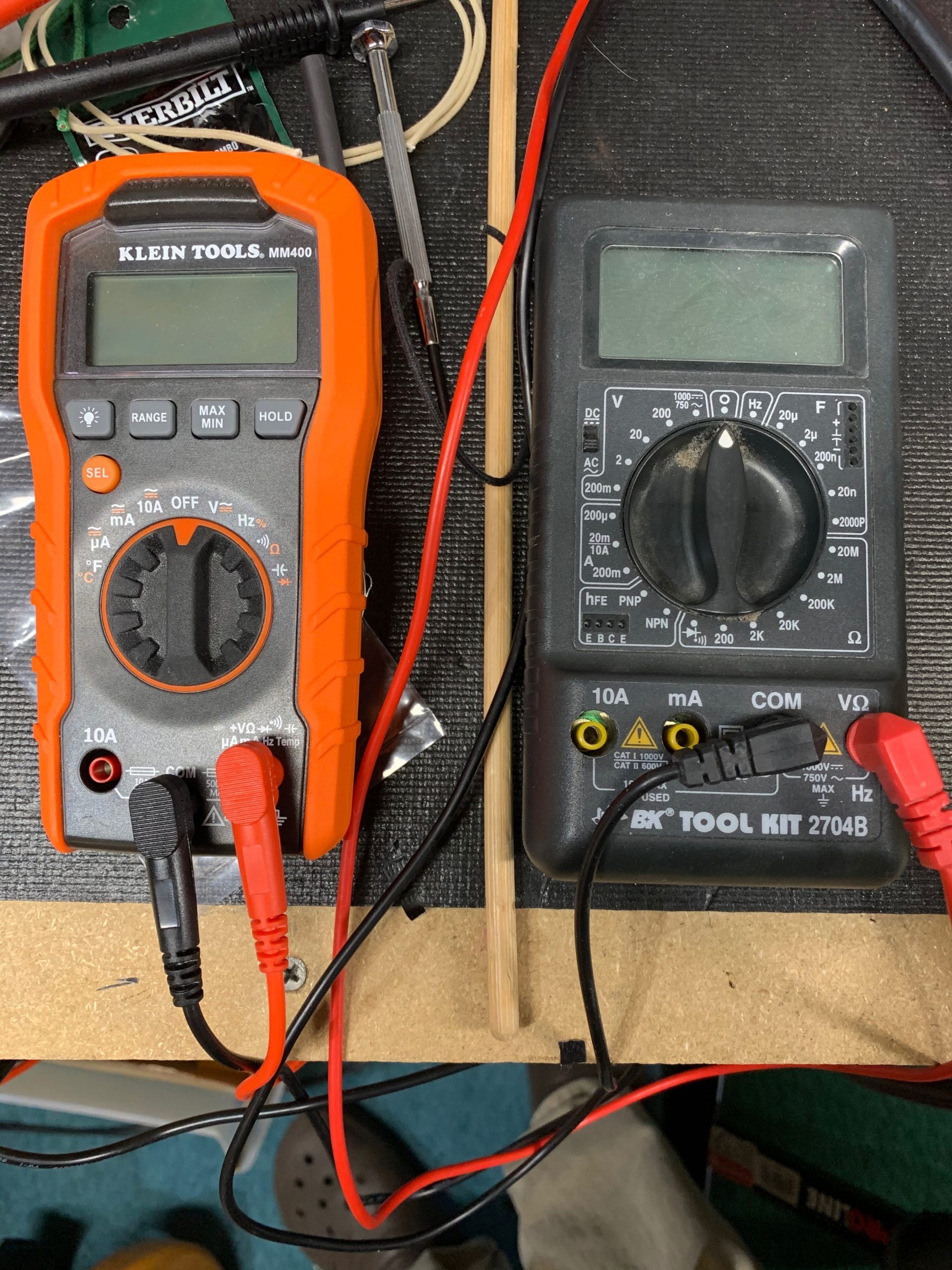
Ok, so I used a different meter and got 5.5 VAC on pin 2 and 3.2 VAC on pin 8. Why on earth my other meter (a new Klein Tool MM400 auto ranging) reads 0 VAC on the rectifier filaments but reads exactly the same on the other filaments as my other meter (3.4 VAC, BK Toolkit 2704B manual ranging) is baffling to me. Anyway, those readings on pin 2 and 8 are too high, they should be 2.5 VAC each, correct? Could that be due to the higher primary too?
Back to the meters. Why would the Klein meter detect VAC at one point, but not at another point where a different is able to detect VAC? The voltages aren’t even supposed to be that different. The meters are shown below.
Attachments:
March 20, 2020 at 12:46 pm #8326KeymasterAs far as the meters go, I dont have any idea about that. I’ve not seen that problem!
I would disconnect the yellow wires from the tube and measure them open. The only reason I can think of for the difference is that pin 8 has a load where pin 2 does not. Even at 5.5, that is a bit high.
It seems that your voltages are just high overall. I don’t know if thats due to a higher input voltage or if the PT you got just has some higher output. Really, around 330VAC on the red is what you are aiming for. 350VAC is high.
March 29, 2020 at 1:47 am #8335Brent
ParticipantMark, I think you need to know how much current you have through the 6L6. Measure the actual value of the cathode resistor with the amp off and carefully measure voltage drop across the resistor with the amp on. Check the cathode to plate voltage (pin 3 to 8).
February 16, 2023 at 2:33 pm #8530Brian
ParticipantHey Mark…. Did you ever figure this out? I’ve got the exact same issue going on with deluxe reverb reissue. Except on the rectifier I’m getting more like 7v on P2 and like 1v on P8. And my DC on P8 is even higher than yours.
I’m wanting to think that it’s an issue with xfmr yellow wires but I don’t understand how it can raise the DC voltage so much. Wanting to feel more confident the yellow wire voltage is the culprit b4 I drop the $ on a PT.
Help! Thx.
February 16, 2023 at 5:03 pm #8531ParticipantHi Brian. I don’t recall. I haven’t touch the amp in years. I’ld have to get it back on the bench to find out. All I know is it’s working fine, though the overdrive isn’t as saturated and smooth as I would like. My bench is in total disarray right now, so I’m not sure when I’ll be able to get it back on the bench to test it.
-
AuthorPosts
- You must be logged in to reply to this topic.