Home › Forums › Design and Building › 2 Stroke Amplifier Design and Building › High(er) Voltage
- This topic has 4 replies, 3 voices, and was last updated August 6, 2021 at 5:13 pm by
 Robin.
-
AuthorPosts
-
May 1, 2021 at 12:53 am #8450
Stephen
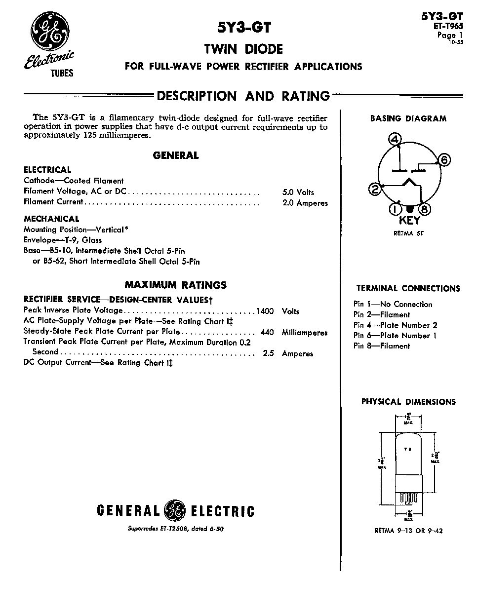
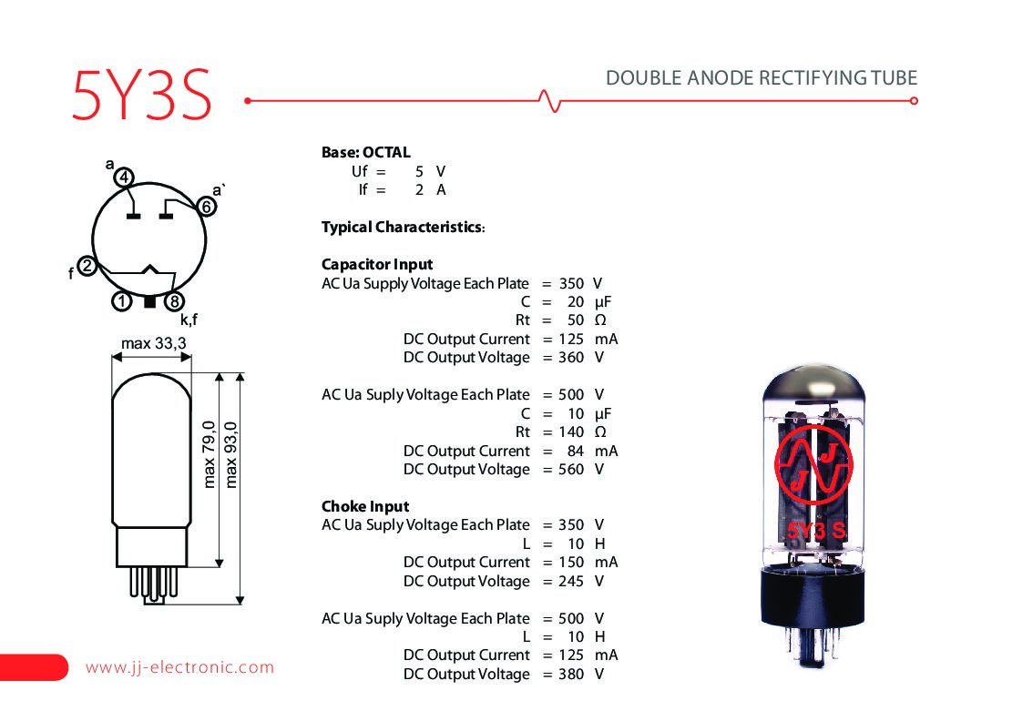
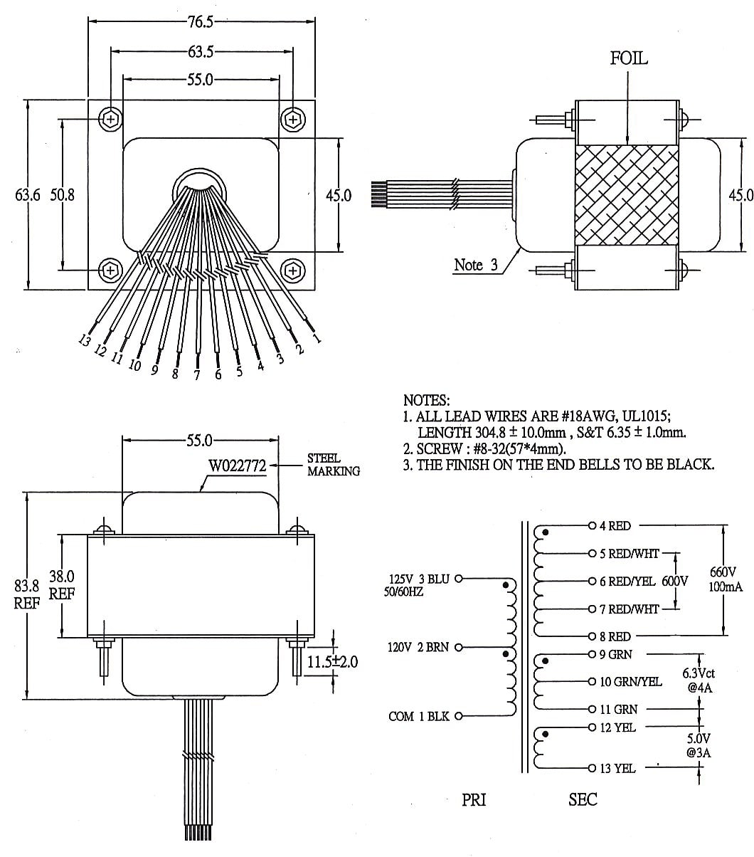
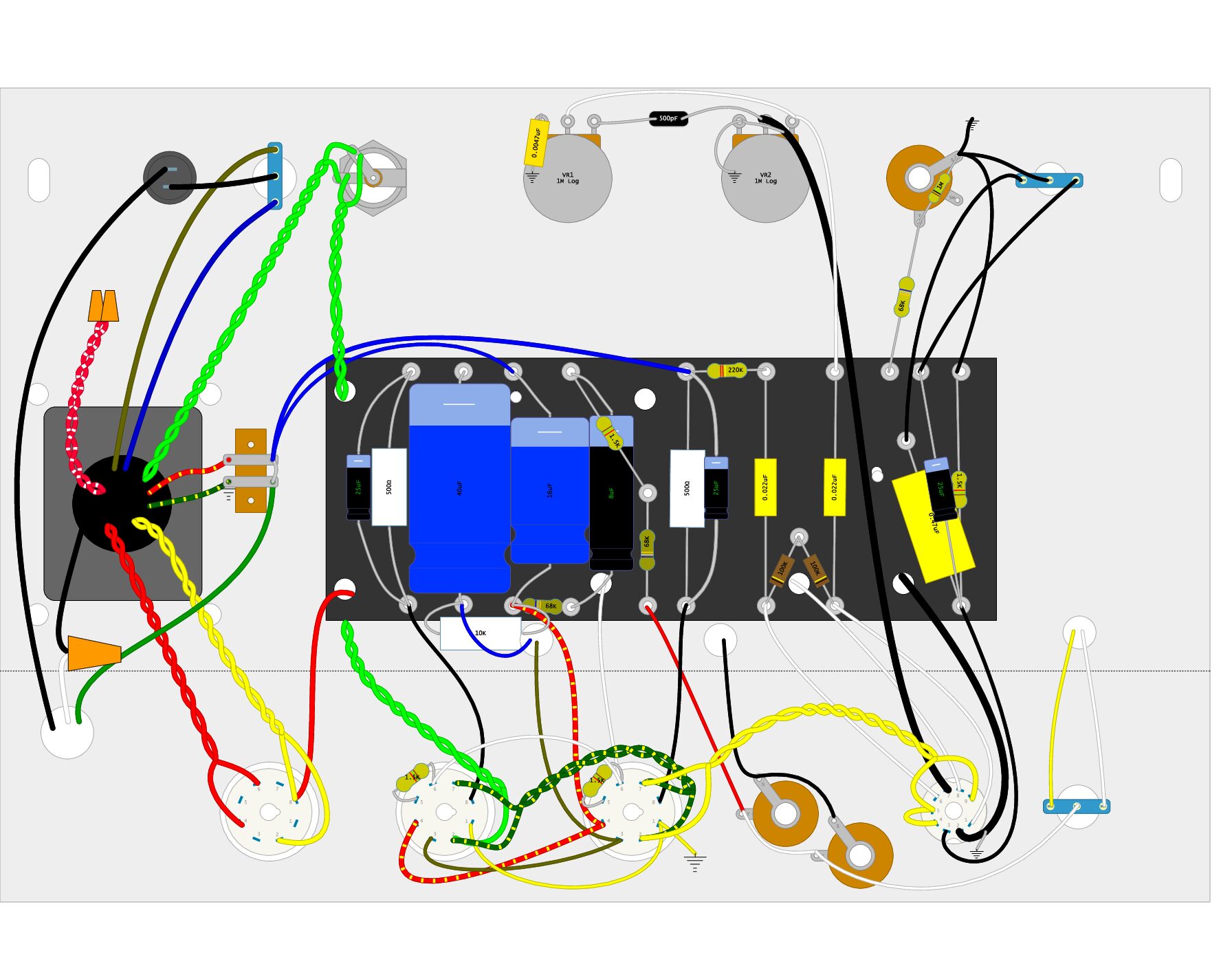
ParticipantI guess I’ll start by stating that my high voltage lines are higher than spec – considerably so. Before I get to the readings, let me list the “hardware” I’m using, as I did not purchase a kit but instead compiled the parts myself from Ted Weber and Antique Electronic Supply. The PT is the Weber W022772 listed in the book. As mentioned in the Addendum on tubeampnetwork, this is one of the newer ones that has both a 120V and a 125V primary. I wired both primaries up to a SPDT (center off) switch of sufficient spec so that I could swap primaries as needed. This PT has two secondaries – one at 300V CT and the other at 330V CT. I initially chose the higher 330V secondary, as I planned to strictly use a JJ 5Y3S or NOS 5Y3 rectifier, avoiding entirely the Russian 5Y3’s that are known to produce higher voltages. I figured this would keep me out of trouble. Of course, this PT has a 6.3V CT heater @ 4A and a 5V heater @ 3A. I stuck with the “original” specs of the amp per the book for the most part (other than the corrected value .0047uF for the tone capacitor), so I have a 40uF 500V Sprague Atom as the reservoir cap, then a 16uF, then an 8uF. I also stuck with the 10k Ohm and 68k Ohm dropping resistors. I couldn’t get a good connection for the grounds with the brass plate, so I reverted to a “star” grounding scheme, routing the grounding connections from the filter caps, output tube bias connections, and 220k Ohm resistor via wires which I connected to the threaded rod that Weber welded to the chassis for the ground bus, which is then connected back to the mains ground wire. The HT and 6.3V heater center taps are also connected to ground. There is no CT for the 5V heater; I understand this is by design so I did not create an artificial center tap for it. The only other major change I made (I kept the 2 parallel output tube option and the old locations for the speaker jacks and impedance switch) was to relocate the switch to being after the fuse, on the black hot wire (as opposed to the white neutral wire where it is in the book) coming from the mains, as it made more sense to me to have both the fuse and the switch located before the mains voltage gets to the tranny or any other circuitry. I chose a JJ 5Y3-S, a JJ 6V6-S, and a JJ ECC83-S (12AX7) as my tube complement. The amp did work, and had great “touch” and tone – just still really loud for an apartment. Couldn’t get it to break up at volume levels that would not make enemies of the neighbors with my rusty playing. More on that in another thread.
With all of that out of the way, here’s what I’m finding. I’m using the 125V primary because my wall voltage is exactly 125V. But my readings were:
355 VAC at each pin (4 and 6) of the rectifier.
500 VDC on pin 8, measuring to ground.
484 VDC at pin 3 of the output tube, measuring to ground
458 VDC at pin 4 of the output tube, measuring to ground
3.1 VAC at each filament wire at the output tube
That puts me at 124 VDC over voltage (484-360) on the output tube plate, 158 VDC over voltage (458-300) on the grid, and 150 VDC over voltage (500-350) on the cathode of the rectifier! I forgot to write down the voltage on the plates of the preamp tube, but they were on the higher end too if I recall.
I ended up doing some disassembly of the amp (for reasons not entirely related, which I’ll post a separate thread for), so once I had the PT secondaries disconnected from their usual connections, I took some more thorough measurements from the PT – obeying electrical safety precautions of course, such as a current limiter and probing with one hand behind my back. Those readings are:
125V primary with 300V secondary = 341 VAC out from secondary
120V primary with 300V secondary = 353 VAC out from secondary
125V primary with 330V secondary = 374 VAC out from secondary
120V primary with 330V secondary = 390 VAC out from secondary
125V primary with 6.3V heater = 6.3VAC
120V primary with 6.3V heater = 6.6VAC
The 5VAC winding varied between 4.9 – 5.0 VAC, regardless of primary selection.
So, obviously the issue seems to lie with the output from the secondaries; they are giving me 13-18% more voltage than what they are rated for. That’s part of the problem anyway. I thought that getting 500VDC from the rectifier was odd, except that if you do the math 500VDC = 355 VAC * √2 (VDC = VAC * √2), it works out. But that would mean the JJ 5Y3S tube is a 100% efficient rectifier. Normally I’d be happy with 100% efficient in anything I do, but it seems problematic here. Especially since the spec sheets for the 5Y3 show the output to be 360VDC with a 350VAC input, which works out to be a rectifier efficiency of 0.7274. I neglected to get a DC current measurement off of the 5Y3 when I had it hooked up. Reviewing the spec sheets further, it shows C = 20uF. I’m using 40uF, which is on the higher end of acceptable for this tube. The sheet also lists Rt as 50 Ohms. The spec sheet for NOS 5Y3GT tubes I found at AES list a 50 Ohm load for the “Total Plate-Supply Resistance per Plate”, so I’m going to assume that’s what the JJ spec sheet is referring to. The NOS data sheet also has a few additional graphs that the JJ sheet does not have. One of which is “rectification efficiency”, which they define as VDC/VAC * √2. So a rectification efficiency of 1 is what I seem to have going on here in my amp. According to the chart though, one can only expect 0-5 mA per plate with this efficiency. A rectification efficiency of 0.7274 would give about 62-63mA per plate – which matches the 125mA DC output current rating of the 5Y3. I’m going to assume that I have 100% efficiency because it was essentially a no load condition – I was not amplifying a guitar when I took the reading, the amp was just sitting there powered up. But wouldn’t they have also measured at no load, and as a result, should have a current and efficiency the same as mine? Something is not right. If I were to somehow get a rectification efficiency of 0.7274 with an input voltage of 341 VAC (125V primary with 300V secondary), I’d have 351 VDC, which is much closer to spec. Assuming the plate voltage would be slightly less, I’d be back in spec on the voltages (340-360 for the output tube plate).
I wasn’t sure if lowering the reservoir cap value to 30 or even 20uF would do anything to the voltage or “efficiency” of the rectifier. According to discussion I was reading on another forum (el34world), the 20uF is a limiting condition given the plate supply resistance of 50 Ohms and output current of 125mA, so if one deviates from the 20uF and goes to a higher capacitance, one needs to reduce the current, reduce voltage, or increase the resistance (or a combination) to make up for it. The data sheets I’ve seen only use the 20uF limiting condition though; there are no graphs or charts that I’ve found that can be used to plot the resistance, voltage, and current based on a different capacitance. Surely I can measure my resistance that the 5Y3 “sees” – which I did – but without a formula to compute the relationship between the current, voltage, and resistance vs. capacitance for this tube type, those readings don’t mean much. I don’t have Merlin Blencowe’s book on valve amp power supplies; I understand it’s out of print. I do have “Designing Valve Preamps for Guitar and Bass”, which is a great resource but sparse on power supply info. But his website, valvewizard.co.uk, does include the formula to compute the total limiting resistance (per anode) in the actual circuit based on DC resistance and voltage measurements of the PT windings. Using that formula and my measurements:
Rlim = Rsec + Rpri × (Vsec/Vpri)^2
Rlim = 128.8 Ohms + 22.9 Ohms × (341 Volts/125Volts)^2
Rlim = 299.22 Ohms if I use the 125V primary with the 300V secondary.
So, I’m well over the minimum of 50 Ohms listed on the spec sheets. Deviating from the 350V, 20mF, 125mA, 50 Ohm spec of the 5Y3 could be done by reducing supply voltage, increasing resistance, and/or lowering current draw in order to utilize a larger capacitance. I just don’t know where to go from there, meaning what levels of each measurement will be balanced and safe, giving me the DC voltage I want. I have a higher capacitance (40mF) and a higher resistance (299 Ohms), a slightly lower voltage (341 VAC), and an as yet unknown current. I’m assuming there’s an actual formula somewhere that takes these specs into account along with the 440 mA design center max steady-state and 2.5A max peak ratings for the 5Y3. I just haven’t found the formula yet, or some form of graph or chart. But with this lower than spec incoming AC voltage, I’m getting a considerably over spec DC Voltage coming from the 5Y3 as stated earlier. Convention leads me to think that adding a resistor of sufficient power tolerance between the 5Y3 cathode and reservoir cap would reduce the DC voltage to an acceptable spec, but I’m assuming it would also reduce my current, which would likely not be good. I wish I had the presence of mind to get a DC current reading off of pin 8 of the 5Y3 when I still had it all connected.
So, what would be the best way to bring those voltages down? Lower capacitance reservoir cap, resistor between pin 8 and reservoir cap, a resistor between HT leads and pins 4 & 6, Zener diode on the HT center tap, replace tranny, or something else that I haven’t even considered? I know this is a lot of info, but I’ve really tried to figure out the problem and possible solutions myself before throwing it out there. I do have a NOS 5Y3 on its way to me from AES, but before I risk ruining a more expensive tube and/or damaging other expensive components, I wanted to see if there was a way to better calculate and understand what’s going on with the voltages. I’m going to try and attach the spec sheets for reference. Thanks in advance for any advice.
May 9, 2021 at 12:47 pm #8456Andy
KeymasterWhew. There is a lot to look at here.
To me, it really comes down to the high primary voltages. I think Id go with the combination that is getting you closest to 330V and let it ride. Some fluctuation is fine. My sense is that you are getting in the weeds with the 5Y3 calculations. This amp is REALLY forgiving. The design can accommodate quite a bit of variance.
It seems like voltages are high throughout and your measurements of the PT confirm that. I think that running it at the 120/300 combination should be fine. The PT might have a bit higher output than specs.
May 9, 2021 at 7:07 pm #8457ParticipantThanks Andy. I know – I went a little too far down the rabbit hole. I was really befuddled. To complicate matters, the amp went silent after inserting a Weber MiniMass into the signal chain, before my teardown and testing. So I was scared that I did irreparable damage to something.
But I’m happy to report that I got it all reassembled, after making a few changes. I added the “pop-suppression” mod to the boost/voice switch. I redid all of the heater filament lines using a tighter twist with the “cordless drill” trick. Finally, I swapped out the 330V primary with the 300V primary on the PT. I redid a few solder points to tidy them up after soldering/desoldering/resoldering. And I replaced my homemade speaker wires with prefab ones. Plugging it in yesterday resulted in sound once again. YAY!
So I made a second attempt with the MiniMass, making sure it was all plugged in correctly. Played for a few minutes in Bypass mode at a low volume, then switched to Attenuate. This time, it worked. So I continued to play, gradually decreasing the volume on the MiniMass and increasing it on the Two-Stroke. I was FINALLY able to get some breakup, and could definitely notice the sag. With the Two-stroke wide-open and the MiniMass down almost all the way, it was really overdriving, getting a great roar from the 6V6. The pop-suppression worked as designed too. I used nothing other than my guitar, Two-stroke, and the MiniMass – no stompboxes. I’ll play around with the output tubes a bit (I have another 6V6 sitting here, plus an EL34 and a 6K6GT) and switch to the NOS RCA 5Y3GT rectifier too just for comparison. But I’m stoked to finally get the full potential out of it as far as output tube distortion and rectifier sag are concerned. I can always put my Rangemaster clone or another stomp in front if I want more preamp sizzle.
I took meter readings today, and between me switching the PT secondary and “whatever else” may have changed in my reassembly, the voltages are now under control. For posterity, here they are:
This is with the 125V primary and 300V secondary:
340-355 VDC at pin 3 of output tube
308-315 VDC at pin 4 of output tube
138-140 VDC at pin 1 of preamp tube
138-140 VDC at pin 6 of preamp tube
358 VDC at pin 8 of rectifier tube
313 VAC at pin 6 of rectifier tube
312 VAC at pin 4 of rectifier tubeObviously, it’s now more “in-spec”, which makes me feel a lot better. I didn’t even have to get too creative with the voltage solutions; I just switched the secondary. The rectifier reflecting a proper voltage drop is especially relieving. With 313VAC going in and 358VDC coming out, it’s much closer to the expected voltage increase (1.1) for a 5Y3 at 1.14 times the VAC.
Perhaps Andy said it best by indicating this is a very forgiving amp. I doubt a SS amp and/or one with PCB’s would have survived the desoldering/resoldering, much less having voltages that were in considerable excess of the specs.
Keep on tubing!
May 10, 2021 at 10:34 am #8458KeymasterWoo Hoo! Awesome! Thanks for sharing the results.
August 6, 2021 at 5:13 pm #8468 RobinParticipant
I have NOS 5Y3s that output 50 volts lower right out of the box compared to a new manufacture 5Y3 or a SS rectifier. I put a 1/2 power attenuator in all my 2Stroke inspired builds these days and it works well, allowing you to dime the amp (for tone) and have an output of around 2 watts. It’s still loud though 🙂
-
AuthorPosts
- You must be logged in to reply to this topic.