Home › Forums › Design and Building › 2 Stroke Amplifier Design and Building › Dumb Question Department…
- This topic has 13 replies, 3 voices, and was last updated June 9, 2012 at 2:18 am by
siliconbronze.
-
AuthorPosts
-
June 1, 2012 at 11:00 am #5151
siliconbronze
ParticipantI recently got my kit, and am completely new to this. I’m still trying to understand the schematic. So here goes the first of likely many dumb questions.
On the schematic, the +Fil and -Fil connections for the 12AX7 appear jumpered together (i.e. Pins 4,9,5 are all connected). I assume I must be interpreting this incorrectly? The layout diagram shows 4 and 5 together, but only 9 going to the heater supply. Where does the -Fil come off, or why does it not need to?
Also, how are the values for all the components chosen? Is there a reference which explains how they are determined?
Thanks!
June 1, 2012 at 12:05 pm #5630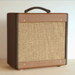 RobinParticipant
Here is a link to the pin outs for the tube sockets used in the 2Stroke (and most others)
:www.dogstar.dantimax.dk/tubestuf/pinout.htm
The 12AX7 is a “dual triode” tube, meaning that it’s actually two preamp triode tubes in one envelope. There are two anodes (pins 1 & 6), two cathodes (pins 3 & eight), two grid (pins 2 & 7), Pin 9 is the center tap for the heater (6.3v) circuit and pins 4 & 5 are for the other side of the heater circuit (which are bridges together in this application). Tube sockets can have the numbers in different places (or none at all) but the pins outs will always be the same for a 12AX7. There is a blank space on the tube between pin 1 and pin 9.
Reading through the first sections of DH’s book will give you an overview of what the components do and how they relate to each other.
Depending on the component, it could be chosen for filtering, voltage control or reduction, tone shaping and so on. Read through the past forum posts here on the TAN site. Many of the posts are regarding the 2Stroke build and you’ll will find some common construction issues.
Everyone hear had a first build once upon a time, so ask all the questions you want, we’ve all been there.June 2, 2012 at 9:37 am #5631Participantthanks alot. I’ll check the forum. Ive been reading DH’s book (but not finished) and other references. I think part of my difficulty has been understanding how the signal (AC) and power (DC) are handled in the amp. Also, I dont get recitifer tubes. I still dont have a firm grasp of it, but I havent given up yet!
RE the heater stuff: so the schematic is wrong? in that pin 9 is not connected to 4&5? Not trying to belabor the point, I just want to make sure Im reading the schematic correctly…thx
June 2, 2012 at 5:22 pm #5632RobinParticipantI’m not sure if you received a schematic with the kit, DH never provided one, but I’ve seen one or two floating around the net. If you look at the chassis layout provided in the book you see that the twisted pair goes from V2 (the power tube) to V1 (the preamp tube), one side connects to pin 9 of V1 the other side connects to pin 4 or 5. Pins 4 and 5 are jumpered together. This completes the 6.3 (heater) circuit in the preamp tube. Heater circuits are not included in most schematics for clarity.
Here is a link: http://www.freewebs.com/valvewizard/heater.html
It is important to understand the use of a tightly twisted pair of leads for the 6.3v circuit and the use of the 100ohm resistors as an artificial center tap if you transformer did not come with one for the 6.3v taps.
The 2Stroke can be hum and noise free if you are careful with the heater circuit and the grounding layout.June 2, 2012 at 7:09 pm #5633ParticipantOK, Im looking at the “revised layout” (downloaded from TAN). It doesnt show anything going to pins 4&5 of V1, other than being jumpered together. There is a 6.3V at V2/pin2. Nothing on the layout specifies a twisted pair. I havent finished reading the DH build instructions, so perhaps a lot of my confusion will be straightened out there?
Are all of the twisted pairs that I see in amp construction for heater circuits? Why do they need to be twisted?
I think I received a weber PT, dont know if it has a center tap for the 6.3V. What exactly is that? Is it a ground (return?) connection for the heater circuit? Is the artificial center tap thru a 100ohm res to ground?
I really appreciate all of this help – if it wasn’t for this site, I dont think this would end well! :0
June 2, 2012 at 9:48 pm #5634RobinParticipantI’m post photos of my finished 2Stroke head, one of them clearly shows the heater circuit. Note that it is a tightly twisted part going from the 2 100ohm resistors to V2 and then V1. Note that in the DH book right next to Pin 4 & 5, it’s says 6.3v. The heater wiring needs to be away from the other wiring in the amp and tightly twisted.
[attachment=47]RC83s.jpg[/attachment]
The other twisted wiring in my amps is just to keep things neat and organized. Only the heater circuit requires the twisted pair for noise cancellation. This is the same concept of noise cancellation that happens with a humbucker pickup.
Refer to the wiring schematic that came with your PT, if you didn’t receive one, go to the Weber website and check it out there. I think the Weber transformer has a center tap for the 6.3v taps but if not, add the 100ohm resistors. Don’t add the resistors if there is a center tap. Also, there is a center tap for the B+ (high voltage) taps that go to the rectifier, that goes to ground too. If the PT includes any other center taps (like one for the 5v taps) DO NOT wire those to ground, just cap it off with heat-shrink tubing or tape and tuck it out of the way. Transformer manufactures sometime change the color of the leads, so it best to get the info directly from them.
Read more about where to wire the different grounds in the amp for maximum noise elimination in the posts here on the TAN site.June 3, 2012 at 10:56 am #5635RobinParticipantThe schematic posted on the TAN site does look as though pins 4,5 and 9 all connect, that is not correct. Pins 4 & 5 and jumpered together and connect to one side of the 6.3v circuit, pin 9 connects to the other side of the 6.3v circuit coming from V2.
June 3, 2012 at 11:50 am #5636Participantthanks for that and the pic of your chassis (which is beautifully done, I might add). If I may, here is a general question. Do all the ground points in the amp ultimately connect to the ground on the plug? Ive been reading some stuff about being careful about how you ground the various circuits (e.g. the DC stuff should be grounded separately from the AC stuff), but doesn’t everything end up going out the ground plug into the wall?
Apparently it’s very important to ground the heater circuit correctly (hi current). I assume the heater “center-tap” (“return”?) ends up going out the ground plug?
June 3, 2012 at 6:50 pm #5637RobinParticipantCheck out this link: http://www.freewebs.com/valvewizard2/Grounding.html
It explains the issues with grounding very well. The 2stroke is a simple circuit and is forgiving when it comes to grounding. That said, there is still opportunities to create more noise (hum) or reduce it. The 2stroke can be very quiet, so building to that goal makes sense. When reading the linked article, pay particular attention to the sections on ground loops and star grounding.
These concepts are true for all electronics, not just tube amps, and can serve you well to understand when trying to sus out a loud hum in a PA system or reducing 60 cycle noise in a single coil pickup equipped guitar. Following DH’s grounding scheme from the book works great.
In the “building a 2stroke head” forum topic here on the TAN site, I mentioned my plans for grounding and it worked out very well. If you are using a grounding plate, per the original design, or attaching grounds to the pot cases, be sure to use a soldering iron that is powerful enough for the job, I would recommend 60w, minimum.June 3, 2012 at 10:34 pm #5638Participantthank you very much…those links are great, that valvewizard page has a lot to read…
June 4, 2012 at 2:40 am #5639RobinParticipantYes, Merlin Blencowe has shared a lot of info in those pages. His books are great too, not as easy going for the beginning amp builder/designer as Dave Hunter’s book, but they are full of useful information.
June 4, 2012 at 2:56 am #5640ParticipantHave you seen or used Morgan Jones’s book, Building Valve Amplifiers?
Do you have a technical background, or self-taught? I’m waiting for my soldering iron and solder to be delivered. Im sure you know all this already, but here’s a nice tutorial.June 7, 2012 at 7:51 pm #5641Andy
KeymasterThanks for noting the issue on the Schematic. When I redrew this for the TAN, I was using one of the ones floating around the net and didnt catch that issue. I’ll fix it and repost it.
Usually, in the kit, I included a Parts List, the Schematic, the revised Layout, and the Addendum to the instructions in the book (correcting some mistakes). I found that building a kit without having a schematic to look at doesn’t help anyone learn. THe schematic is where you can really see the signal flow and how everything works.
June 9, 2012 at 2:18 am #5644ParticipantNo problem. I appreciate having the schematic, as it gives me a chance to learn how to read it! All great stuff. Best wishes.
-
AuthorPosts
- You must be logged in to reply to this topic.