Home › Forums › Design and Building › 2 Stroke Amplifier Design and Building › Older kit, need coherent instructions
- This topic has 19 replies, 3 voices, and was last updated March 19, 2021 at 3:29 pm by
Andy.
-
AuthorPosts
-
February 24, 2021 at 5:30 pm #8382
YankeeDespot
ParticipantHowdy,
I bought the 2 stroke kit here years ago, and am now just getting around to building. I know some parts are different from the book,(which I have of course), but the supplied addendum is incomplete or wrong. In the discussion of the new PT, he seems to mean the OT, and none of the descriptions of the PT match what I have. Mines closest to the one in the book, but doesn’t have extra yellows or the green/ yellow. I did the best I could, but somethings not right. I’ve triple checked everything, and it’sgood.Hen I fire it up through a variac at 115 vac, I get 330 ac coming out of the PT, but no dc voltage coming out of the rectifier tube.
I’ve ordered another 5y3s. Any other ideas?Also, are there different instructions? For example, my pt has no green/ yellow wire to go to ground.
My first amp so be gentle.Thanks. Doug
February 27, 2021 at 9:34 pm #8383Andy
KeymasterHey Doug,
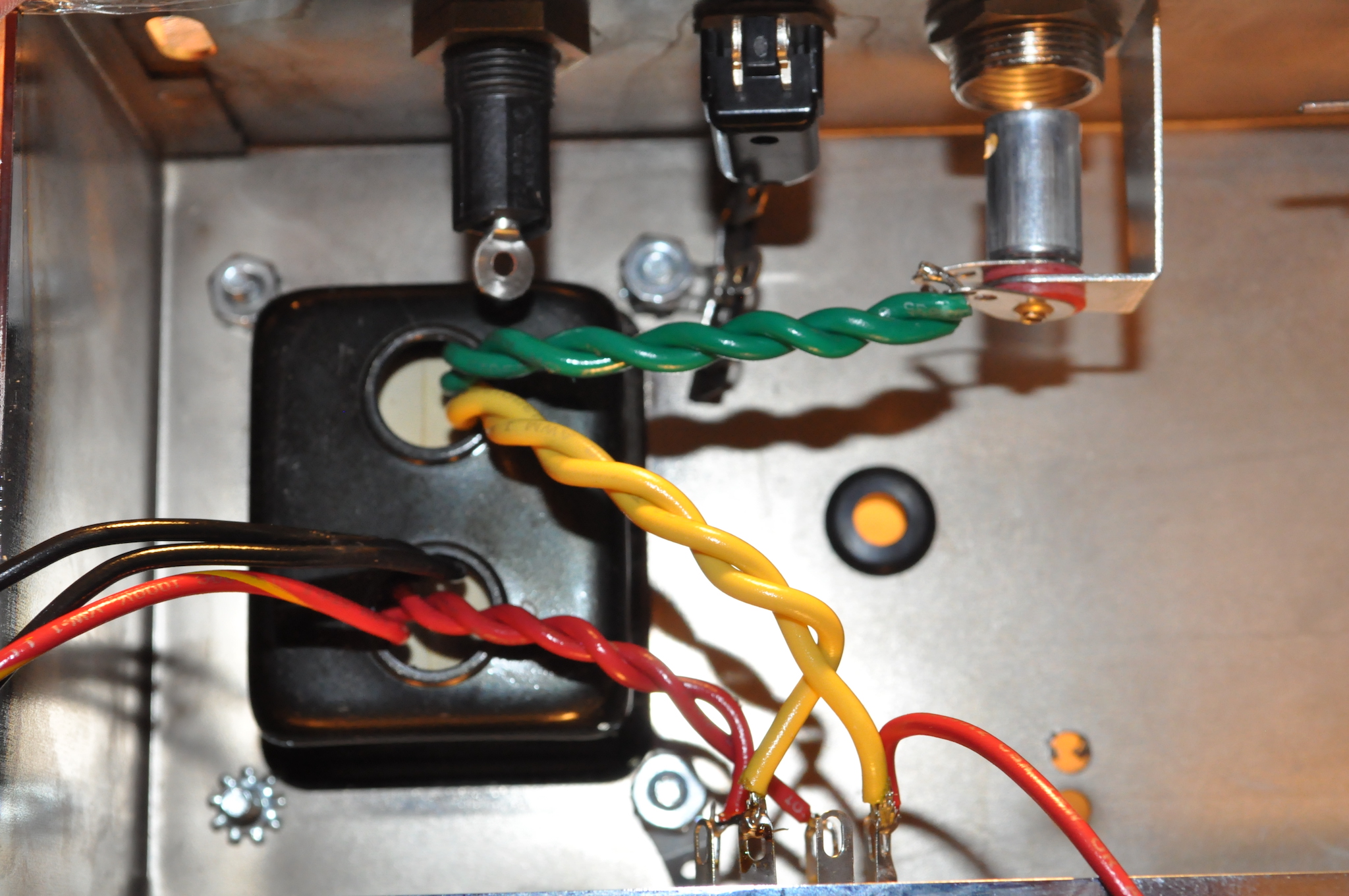
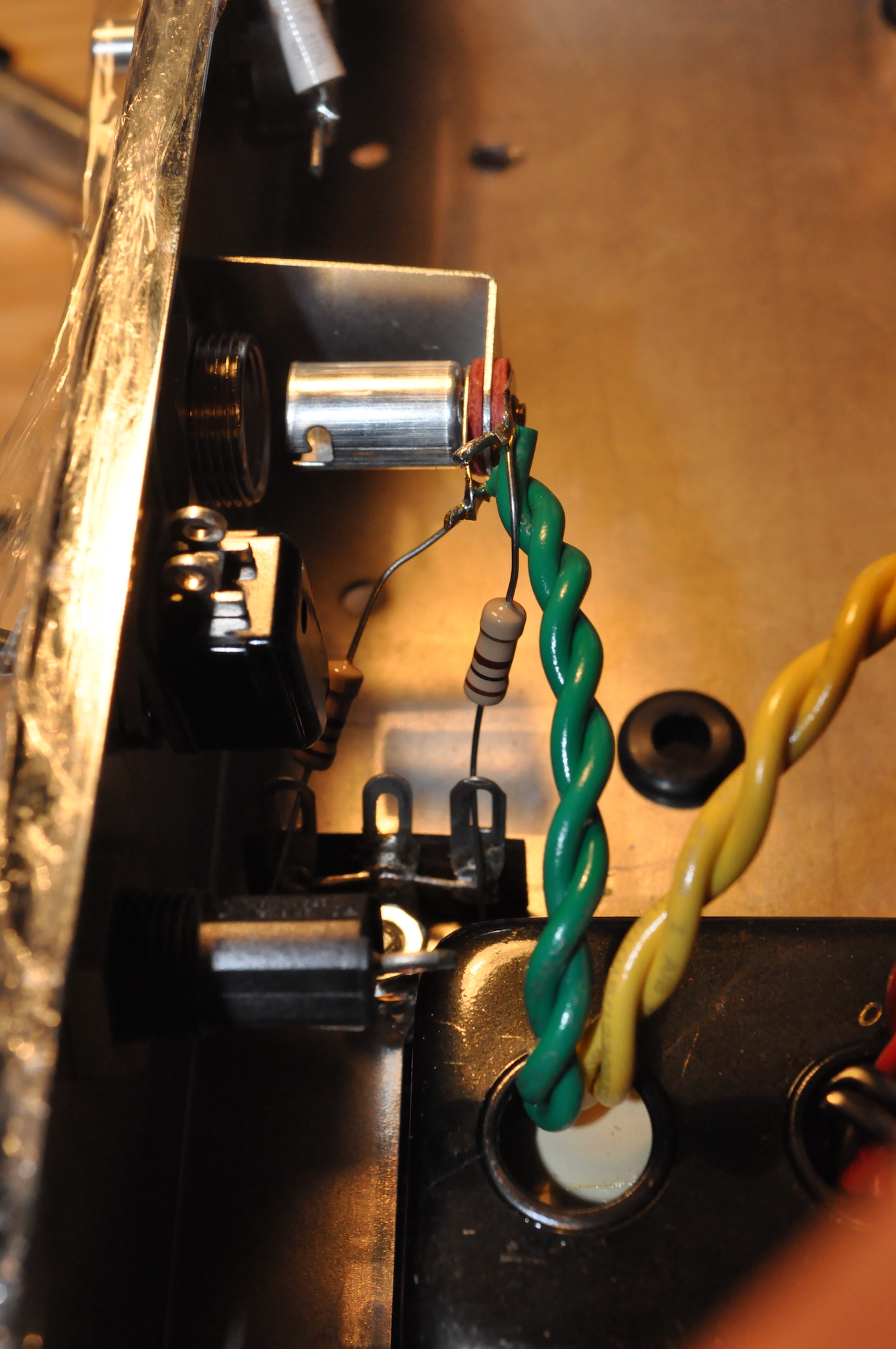
As far as the Addendum goes, he is referring to the Power Transformer. The letter that came with the kit explains a bit about the current Power Transformers that are available. You have to make an artificial center tap, which is shown in one of the attached images. The newer PT’s went away with the center tap on the filament line, so you will need to connect two of the 100Ω resistors from those green leads to ground.
I don’t think that is the problem though. The other image shows the red and yellow leads should be wired to the pins of the Rectifier. It doesn’t show where but the red goes to 6 & 4 and the yellow to 8 and 2.
Black will connect to the switch and fuse.
If those are different colors than you have on the PT, let us know!
Attachments:
February 28, 2021 at 7:45 pm #8386ParticipantHi,
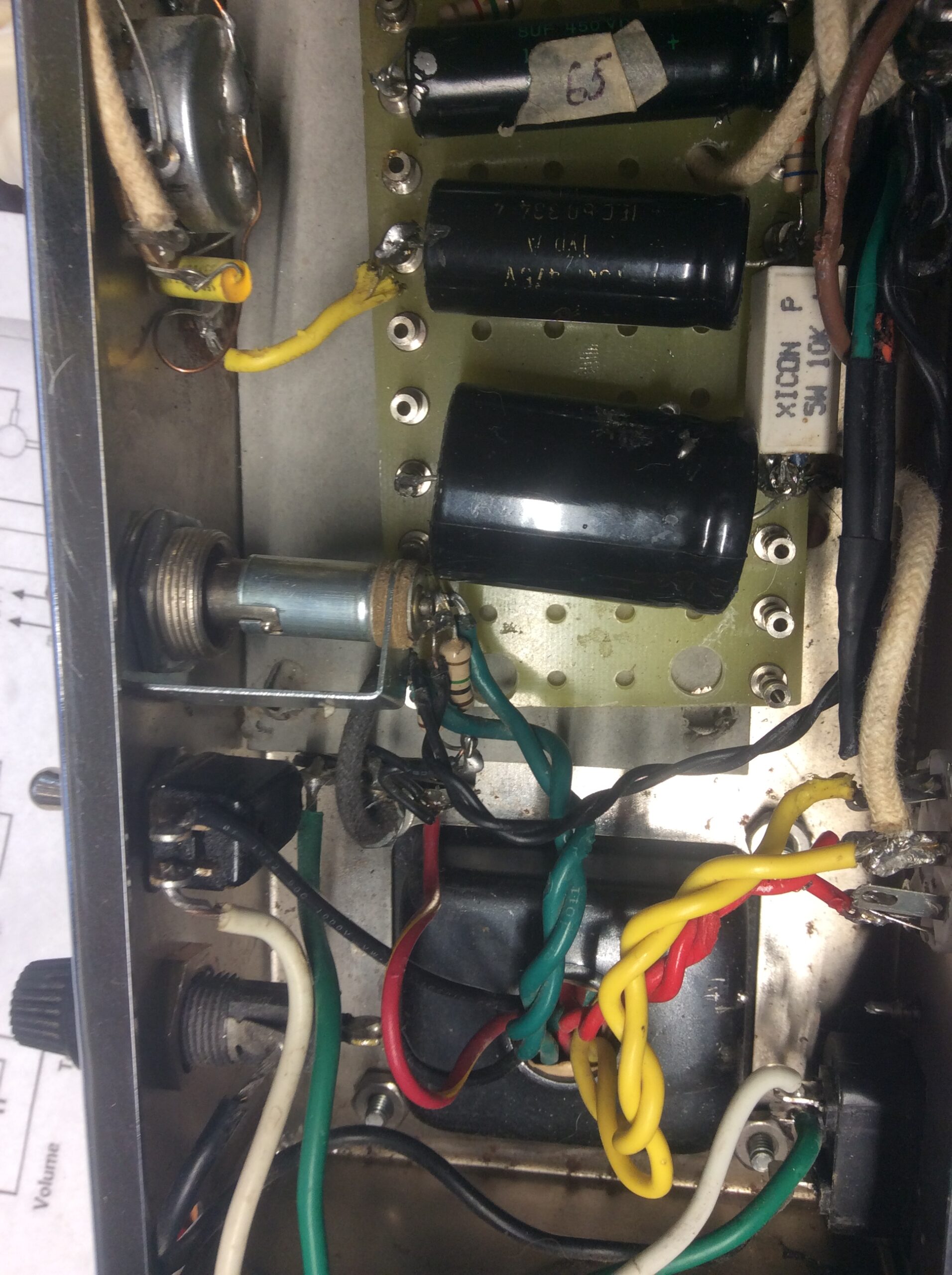
I think we’re mostly on the same page. I have the center tap done, and my low voltage ac is ok. The problem is that there’s 330ac on the yellow wires going into rectifier tube pins 2&8, but no power coming out of pin 8 to the first filter cap. I have a white cloth covered wire going from pin 8 to the first cap and on the same post, the 5w/10k resistor.
So, assuming that’s wired right, I’m assuming the rectifier tube is bad. Agree?
Thanks a lot. I’m gonna get this sucker runnin!Doug
Attachments:
March 1, 2021 at 10:42 am #8388KeymasterIt’s possible that the tube is not functioning. Id probably look first for some open joint or misplaced ground somewhere before I replaced it though. Make sure only the places that are supposed to be grounded are grounded.
Also… It looks like there is a 1 MEG resistor at the center-tap place not a 100Ω. If you swapped those you could have some issues. 100Ω is Brown Black Brown and 1M is Brown Black Green
March 1, 2021 at 3:25 pm #8389ParticipantAndy,
I’ll go back through it, check the values and grounds, and let you know. I ordered another tube, so I’ll have that option/ diagnostic tool as well. I’m learning a lot, as I guess all new builders do. I just don’t know what I don’t know. I’ve got questions on the impedance switch, but will try to get it running first.
Thanks for the help. It’s greatly appreciated.March 4, 2021 at 6:54 pm #8393ParticipantI have a clue or two.
So I tried another new jj 5y3s tube in rectifier, and still no joy.
I have 345 vac going to pins 4 and 6 from the red pair, and 5.3 vac from yellow. But as before, there’s apparently no output from pin 8.
At the junction of the first filter cap, 5w resistor and blue OT wire, I only have 320 milli volts DC.
The pilot light lights, and there’s low ac voltage to one leg of the power tube(s)From the lamps, the innermost (I’m guessing positive) lug reads 6.5vac, while the second, negative lug doesn’t have any voltage. All these readings made with the neg probe of the multimeter clamped to the chassis. Correspondingly, there’s 6.5 at pins 4+5 of v1, but none at pin 9. There’s 6.3 at pin 2 of v2, but none at pin 7. The tubes light but dimly. Rectifier I get 5.2 at pin 2 but nada at pin 8.
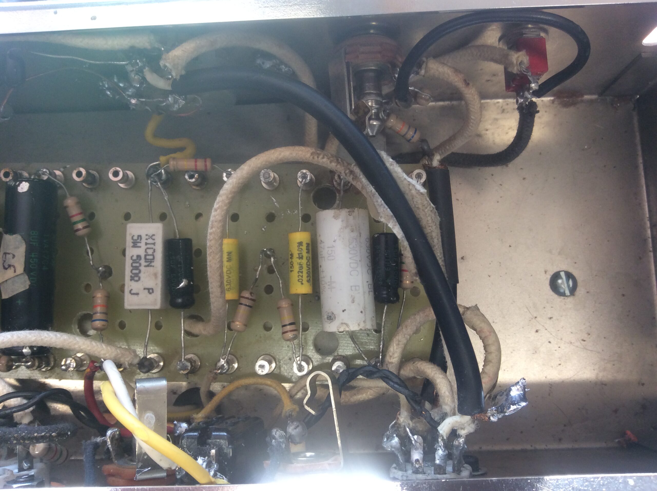
My first question regards grounding the filter caps. The diagram shows just the 18uf cap being grounded, but does that dotted line underneath mean all three should be on a grounded bus? I tried both way, made no difference I could see.
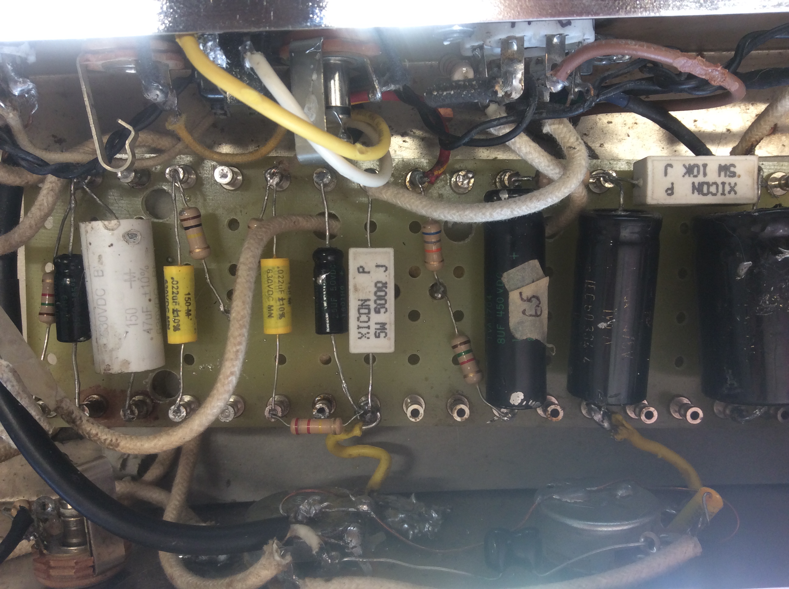
I’ve attached some pics. I know I’m asking a lot, but I’m ready to throw this thing in the ocean. That’s pretty bad, cuz I live in Arkansas so will have to drive a thousand miles to do that.All hints helps and even criticism greatly appreciated.
Doug
March 6, 2021 at 9:17 pm #8397Stephen
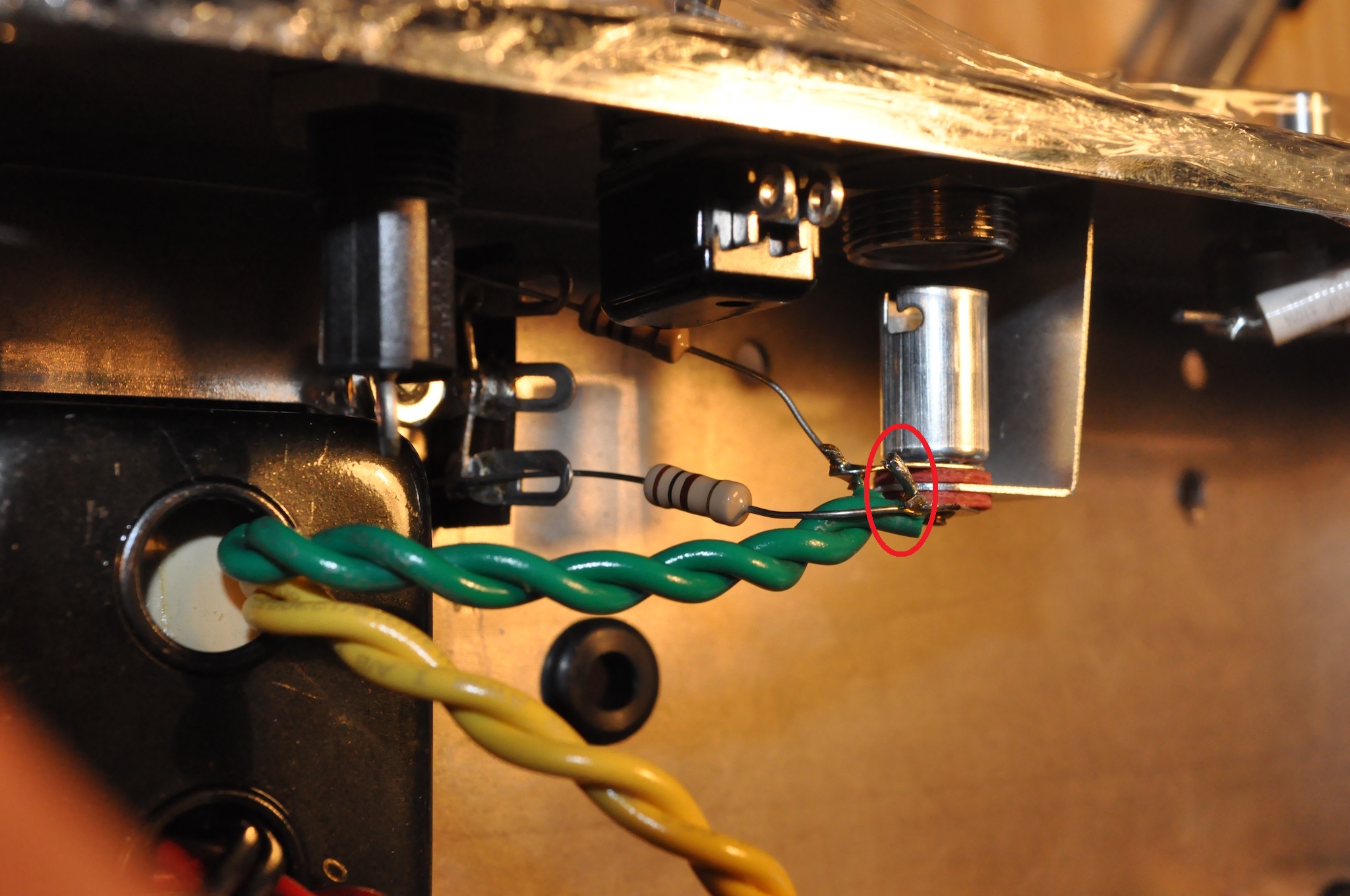
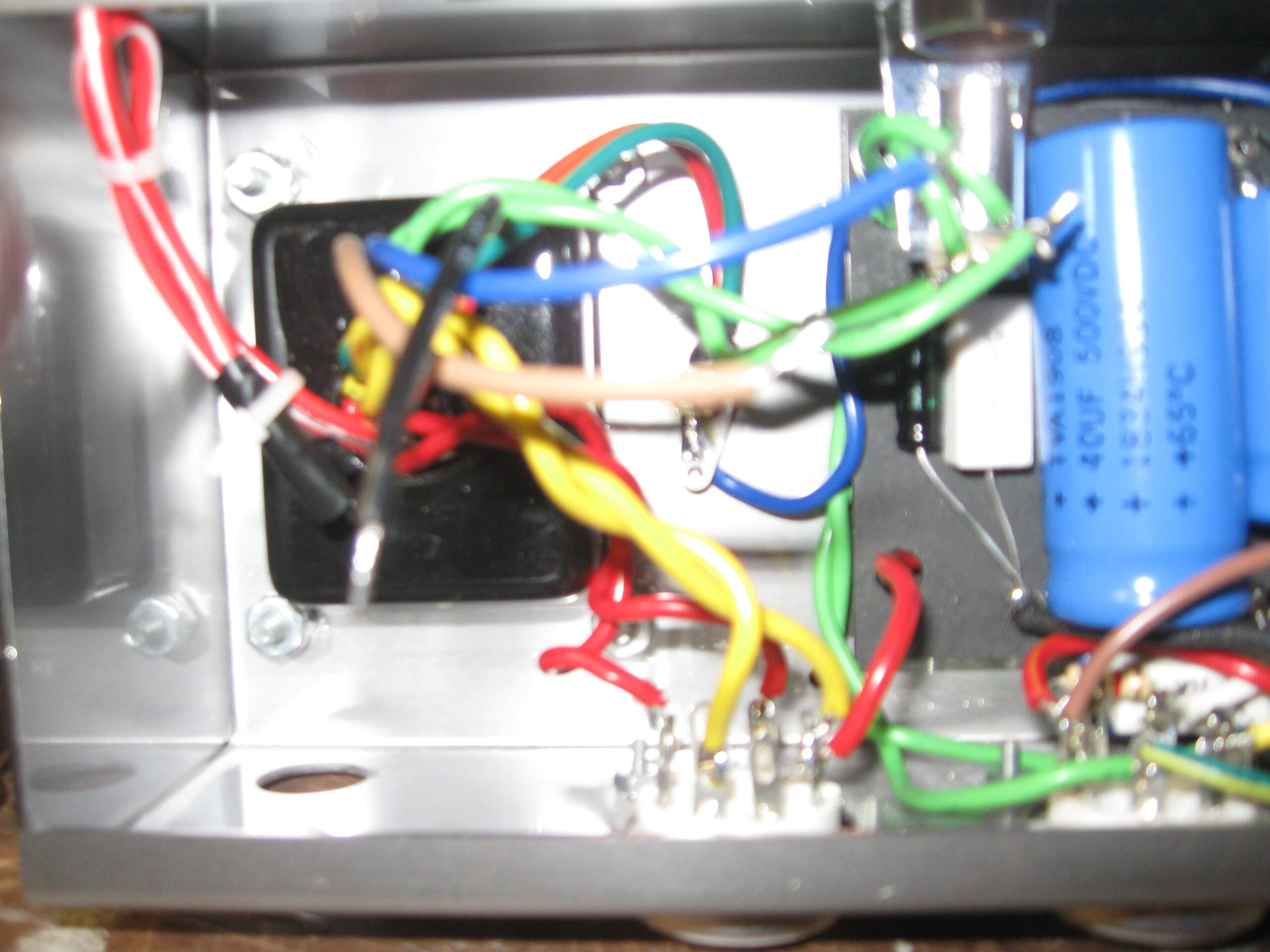
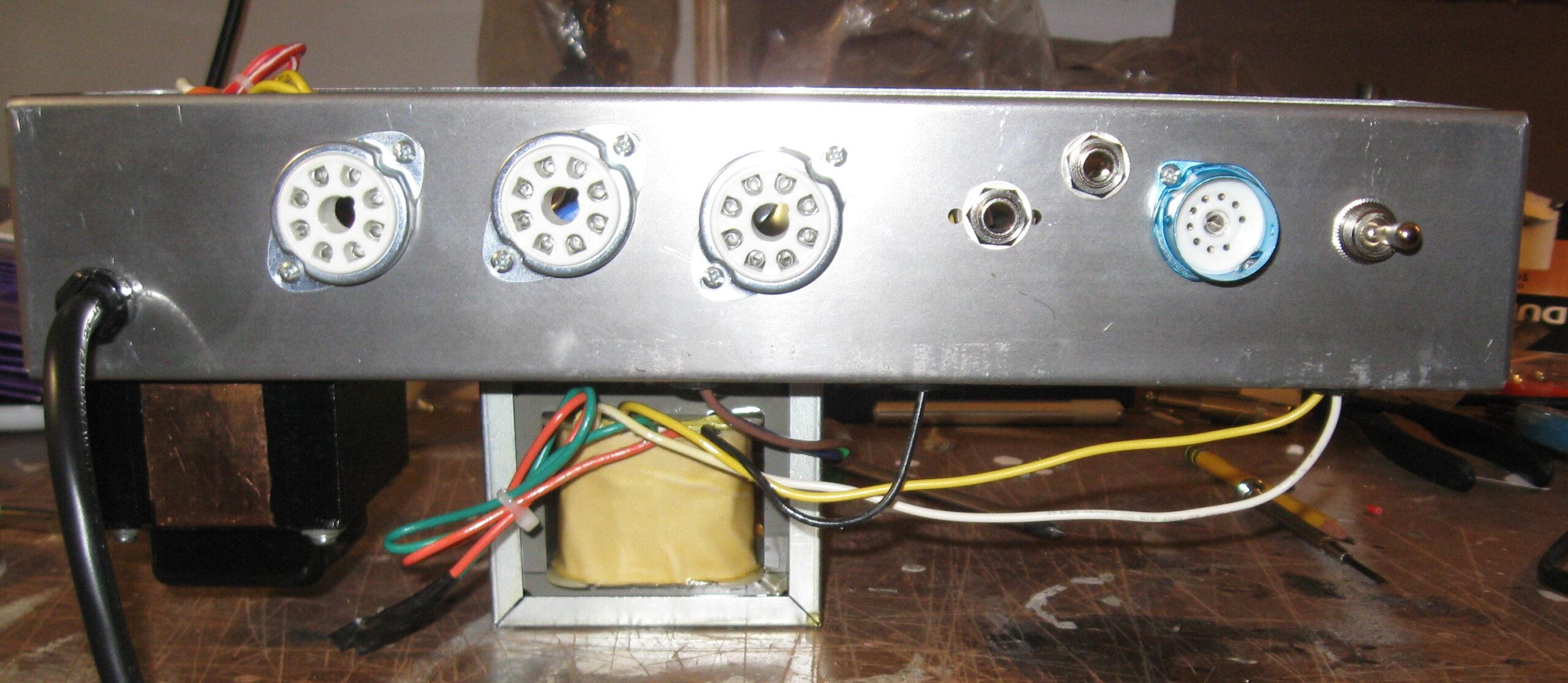
ParticipantOne thing I noticed about the filament wires going into the lamp. In the photos you have from PRIOR to the attachment of the outgoing filament wires (from the lamp to the first output tube), it appears as though the end of the lead (circled in a modification of your photo) going to the “tip” of the lamp holder may be touching the “sleeve” solder lug of the lamp holder. In the later photograph AFTER those outgoing leads to the output tube, you had rotated the lamp holder 180 degrees to allow the installation of the first giant filter cap, so I cannot see them in that photo. Unless you clipped off the protruding wire from the lead going to the “tip”, it may be touching the “sleeve” slug still – I can’t tell because it’s on the far side now, obscured by the lamp holder in the photo. If the two touch, maybe that’s why only one lead has 6.3 VAC on it? Just an idea to check. That of course does not explain the absence of HT DC coming off of pin 8 of the rectifier. Check your multimeter settings. Mine has separate voltage settings for DC voltage and AC voltage, which may make a difference in whether or not it detects and/or displays any voltage. Also, make sure that the correct pin numbers were used, since on the rectifier, the odd-numbered pins are not used. I can’t see the “index slot” in the tube socket in the photos, so I would merely suggest checking to make sure you did not accidentally rotate the wire locations by one pin in either direction, which would definitely cause the 5Y3 tube to not rectify. Or accidentally rotated the socket by 180 degrees. I attached a photo of the bottom of my chassis to show socket orientation, and a (sorry, blurry) photo of the rectifier connections while I was still in the process of building. Does its filaments glow at all? You’ve got the HT center-tap going to ground, so no issues there unless it’s a cold solder joint or something. I struggled soldering some of the connections due to tight clearances, but was fortunate enough not to melt any cap casings.
Attachments:
March 6, 2021 at 9:19 pm #8400ParticipantThe one chassis photo failed to upload the last time. Trying again…
-
This reply was modified 3 years, 4 months ago by
Stephen.
Attachments:
March 6, 2021 at 9:29 pm #8403ParticipantMaybe third time is a charm on the socket orientation? I made the file smaller by cropping it…
Attachments:
March 6, 2021 at 10:04 pm #8406KeymasterThe dotted line represents a connection. The three power caps and the 1.5k resistors all connect (negative side) and then go to ground. Is that connected on your amp?
March 10, 2021 at 5:19 pm #8411ParticipantI promise I’m not stupid, but I am left handed. I looked at the diagram from the perspective of outside, so all my tube wiring was backwards. Yikes. I’ve used the lightbulb and a variac, so hopefully we’ll be ok. I’ll rewire it, and check grounds and cross fingers and toes.
Thank you all for the assistance. I make pretty good acoustic guitars, so I’ve learned that my strengths lie in that area more than amp building.The help I’ve gotten is great. Thanks again. I’m determined to get this running!
DougMarch 10, 2021 at 5:23 pm #8412KeymasterSee, Im the opposite. I’ve built a few guitars but always miss something crucial. But on amps I’m much more accurate 😉
March 10, 2021 at 7:39 pm #8413ParticipantOh snap, that would do it. I checked some voltages on mine to see and I’m getting 3.1 VAC on each lead for the filaments. So once you get all the connections right, you should be in that ballpark. Mine works, but in checking things to respond to this post I discovered a problem of my own. I’ll start a new thread for that if I cannot get it on my own. And likewise, I’ve done only some minor hardware replacement on guitars -nothing big. The bad thing about electrical – you can do almost everything wrong, yet it still may work. Lol
-
This reply was modified 3 years, 4 months ago by
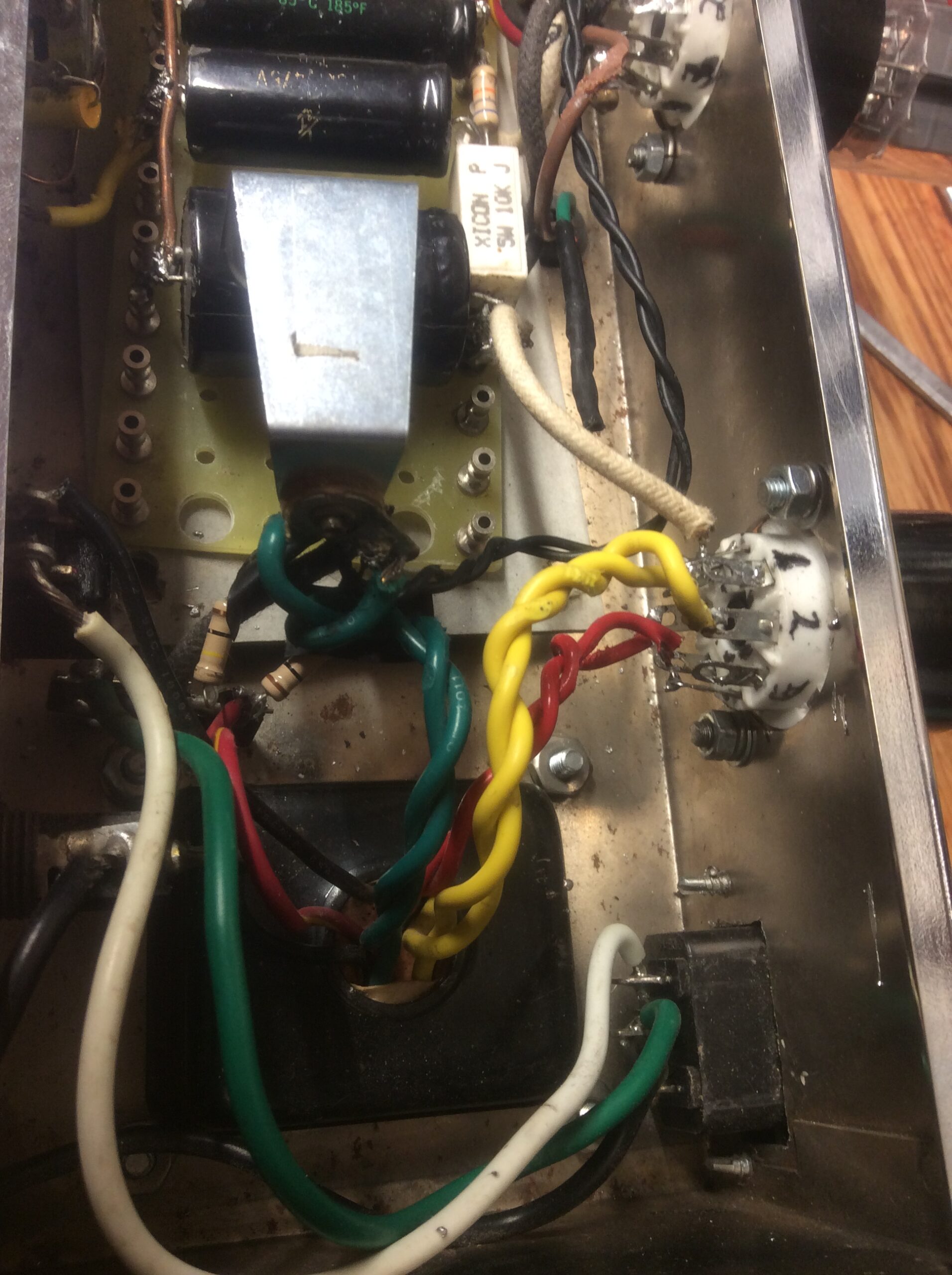
March 13, 2021 at 2:54 am #8419ParticipantUpdate. I have dc voltages on the filter caps that look ok, at 376,338,and 241 big to small. DC
On a 6V6 there’s 373vdc at pin 3, and 340vdc on pin 4 with 122 vac from my variac so that’s all high, but there’s hum to the speaker now, that doesn’t change with volume or tone, and scratching sounds from the speaker when the tube pins are probed. I’ve input guitars and sine wave signals, but none of that comes out.
At the 100k resistors from the 12ax7, I get 150 and 153 vdc. Feels like a win
thats the good news.
My filament situation is Fugese. The yellow wires that should supply the 5v ac to the rectifier are showing 380vdc! The red pair at 330vac.
At the lamps, one green wire shows 6.5vac, and the tube pins on that wire show 6.5vac. The other wire has no voltage, and so the corresponding tube pins don’t either. The tubes do in fact look half- bright.
unsure if it was doa or if my mistakes cooked the pt, but it seems to be malfunctioning. I’ll look up ways to test them, and any ideas and suggestions from y’all will be appreciated.
This amp will run!
thanks. Doug
Attachments:
March 13, 2021 at 2:45 pm #8421KeymasterIve never measured (or I dont remember that I have) the VDC on the rectifier filament lines. What AC are you getting there?
Check the filament lines (green) for a connection to ground. For the one that doesn’t work. Need both of those to fire to get amplification.
-
AuthorPosts

- You must be logged in to reply to this topic.