Home › Forums › Design and Building › 2 Stroke Amplifier Design and Building › Wires in the Two-Stroke kit
- This topic has 9 replies, 2 voices, and was last updated July 7, 2012 at 1:10 pm by
 Robin.
-
AuthorPosts
-
July 1, 2012 at 7:09 am #5141
siliconbronze
ParticipantCan anyone shed some light on what wire to use where? I received a few lengths of wire in my kit, two cloth insulated lengths (black/white), a length of shielded black cable, some speaker cable, and thats about it.
I assume the cloth stuff is for the heaters and will be twisted?
Where should I use the shielded wire?Clearly I will need more wire, as the layout indicates wires of different colors. I am assuming that all of this should be 20GA?
Also, the book recommends attaching the flying leads to the eyelet board when you solder the components on.
1. What is a safe length to make these?
2. It seems that a couple of the eyelet holes are going to be crammed with wires (3+ components + flying leads) – am I understanding this correctly?Thanks very much in advance.
Addendum: After RTFM (DH’s book), I see he mentions the shielded wire. I guess I dont understand the reasoning behind where it should be used and where it doesnt matter….
July 2, 2012 at 8:57 am #5576 RobinParticipant
The cloth insulated hookup wire can be used for everything in the amp, Fender did it that way for many years. I expect Andy has provided enough wire for the required leads. Various colored wire is great for keeping track of what goes where but is not required. 20ga wire is the preferred gauge for tube amp leads, expect for the heater circuit (6.3v) where 18g is preferred. What came with the kit will suffice. A couple of things to keep in mind when working with the wire leads: Be careful not to nick the wire when stripping the insulation away. Nicks will create a stress point that can weaken and break later (no fun to have to repair on an eyelet board) and keep the leads short.
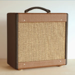
The shielded cable is an “upgrade” to provide interference protection between the input jack and the preamp tube. The center lead connects from the tip lug of the input jack to pin 2 of V1. The 68k resistor can go on either end. Note that the braided shielding of the shielded cable goes only to ground and does not connect to the inner lead. The shielding should connect to ground on only one end (trim the other end short and tape it or use heat shrink tubing to keep it from touching anything). If both ends are grounded, it creates a ground loop and induces hum. Shielded cable can be used in other parts of the signal chain, but is not necessary in the Two Stroke.
Although the photo is not eyelet board construction, you can see how the shielded cable is used between the input jack and V1, also, the whole amp is wired with yellow cloth insulated hookup wire (expect the heater circuit which is a green twisted pair).
[attachment=59]wiringdetail.jpg[/attachment]
Sometimes it’s necessary to connect multiple wires in one eyelet hole, remember you can use both sides of the board and it should work out.
Study the photos posted in the photo section of the forum for some good (and maybe not so good) examples of how to do it. A web search of Fender amp chassis photos should provide a wealth of examples.July 2, 2012 at 10:17 am #5661ParticipantThanks so much for the help. Thats a beautiful looking board. Ill check for the photos.
July 4, 2012 at 11:26 am #5662RobinParticipantCheck out this example of an eyelet board Two Stroke:
[attachment=60]alanstwostroke.jpg[/attachment]
This is from Alan D.’s photo album here on the TAN site. Building neat and clean allows you to find issues and do mods more easily later on.
Note the 68k resistor between the shielded cable and the input jack.July 4, 2012 at 11:43 am #5663ParticipantThanks, that’s very helpful. It looks like he’s got the leads to the lamp twisted – does this help somehow? Of just for neatness?
Another “newbie” question: I assume we dont want to use smaller gauge wire (e.g. 22), but is it OK to use larger gauge wire, e.g. 16 instead of 18? I cant imagine it would be a problem, but maybe there some EM interference issue or something like that…
Also, in the non-eyelet board earlier, what are those pieces to which all the components are attached? Somehow they protrude over that board?
Thanks.
July 4, 2012 at 12:34 pm #5664RobinParticipantThe green twisted pair from the pilot light to the power tube is important as is twisting the rest of the 6.3v circuit. Twisting the pair of wires together allows them hum cancel. Keeping the 6.3v wiring away from the rest of the signal chain is helpful too. There are recent postings in the forum about heater circuits.
Larger gauge wire is fine, it’s harder to work with and fit into the eyelets and lugs. I use 16g for speaker wiring.
That’s “turret” board construction on my 2Stroke. I wanted to try that after a couple of eyelet board amp builds. I’ve built several turret board amps and would do it again. I like it better then eyelet boards because you can make component changes easily, attached more leads and the boards are fun to make. You can get turret board construction materials a lot of places, I get mine from Hoffman Amps.
Here is a better view of how the turrets stand off the board. This is from my 15w amp build.
[attachment=61]15wboard.jpg[/attachment]
July 4, 2012 at 8:21 pm #5665ParticipantNice! Did you bump up the two stroke to 15W? How did you do that? or is this a different circuit altogether?
July 5, 2012 at 2:58 am #5666RobinParticipantIt’s a different circuit all together, 2 EL-84s with a phase inverter.
Based on a Vox AC-15 or Matchless Spitfire. Very clean and chimey,
great with pedals. I play out with it all the time, really a fun amp.July 7, 2012 at 3:21 am #5669ParticipantThree questions:
I don’t see the output transformer on the layout diagram. I looked at some pics here, and I dont see it in these pics (at least in the pics I saw). I assume it’s there somewhere because I got one in my kit? :0
And, the boost switch on the layout diagram doesn’t show the 1M resistors to ground. Is this common, in that not every component is shown on the layout diagram?
Finally, V1 pins 4 & 5 are tied together on the layout diagram (heaters for both sides of the tube?), but dont go anywhere. I assume this is either the positive or negative heater supply. From what I understand, the heater circuit is just a simple loop from the 6.3V taps on the PT. Does it not matter which pin is + and which is – ? Should I run the heaters for both V1 and V2 in series?
Thank you!
July 7, 2012 at 1:10 pm #5670RobinParticipantReview the photos of the various Two Stroke amp builds in the photo section to see how others have mounted the OT, the OT leads connect as marked “To OT” on the chassis layout. Review the schematic in the TAN wiki, it clearly shows how the OT is connected. Read DH’s explanation on the how to connect the secondary leads on the OT and wire the impedance switch accordingly.
The resistors to ground on the boost switch were not part of the original design, they were added to pre-load the “boost” caps and diminish the amount of pop heard when you select one of the boost settings for the first time when the amp is powered up. You could leave them off, experience the pop and then add them later. View the “Maggie” kit schematic on the Weber SVT website for another view of how the switch is wired.
The heater circuit is most often not shown in tube amp circuit layouts and schematics (but sometimes it is) for clarity as they are just about all the same. Review your “Dumb question dept” topic, the resources mentioned there offer a complete explanation of heater circuits.
-
AuthorPosts
- You must be logged in to reply to this topic.